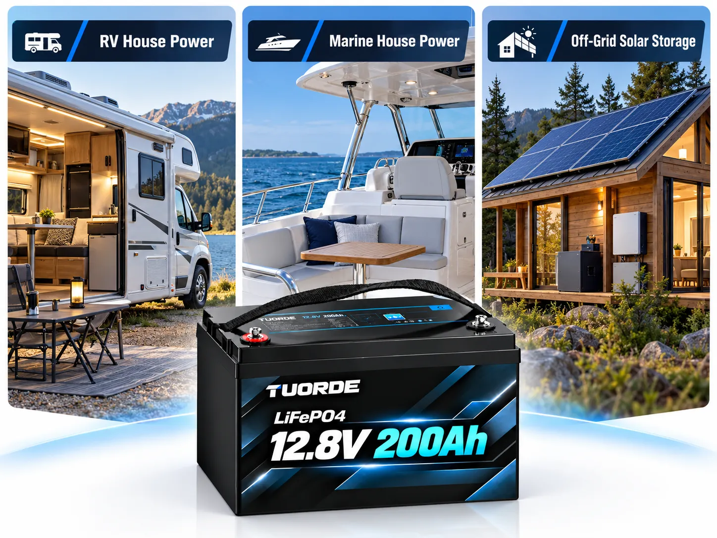
Plan your LiFePO4 upgrade for RV house power, marine house-battery systems and off-grid solar storage.
Start with your daily energy demand, charging sources and installation conditions. TUORDE supports battery brands, distributors and system integrators with application-specific configuration review and OEM / private-label cooperation.
LiFePO4 replacement application illustration. Select the battery configuration for the actual installation.
01 / CHOOSE YOUR APPLICATION
Three Deep-Cycle Replacement Routes
Start with where the battery operates, the loads it must supply and how it will recharge. RV, marine house power and off-grid solar storage share an energy-storage task, but need different integration reviews.
RV House Power
For motorhome, travel-trailer and camper house loads such as refrigeration, lighting, fans, pumps and compatible inverter-fed appliances.
Selection focus: daily Wh, time between charging stops, inverter demand, battery-bay fit and charging while parked or driving.
Marine and off-grid projects use an application-specific review route. The RV listings below are reference platforms for RV duty and do not establish marine suitability or stationary-system compliance.
MARINE / HOUSE & AUXILIARY ENERGY
Plan the House Bank Around Life on the Water
Define what the house bank must power while at anchor and underway. Review the battery together with charging sources, installation location and the vessel’s service requirements.
Marine requirement
Information to provide
Review outcome
House-load energy
Refrigeration, lighting, pumps, electronics and other loads, including standby use and time at anchor.
Daily Wh, operating reserve and a reviewed bank capacity.
Charging sources
Shore charger, solar controller, alternator/regulator and existing starter/house isolation arrangement.
Compatible charging limits, current control and behavior if the BMS stops charging.
Installation environment
Battery-bay photos, mounting, moisture/salt exposure, temperature and access for inspection.
Reviewed enclosure/environmental requirements, retention, protected terminals and service access.
Essential services
Identify circuits that must remain available and the existing reserve/backup arrangement.
Agreed response to low energy, battery isolation or a BMS disconnection; review by the vessel’s installer.
Model & documentation
Vessel type, system voltage, target market and required installation/compliance documents.
A model-specific suitability review and documented configuration before ordering.
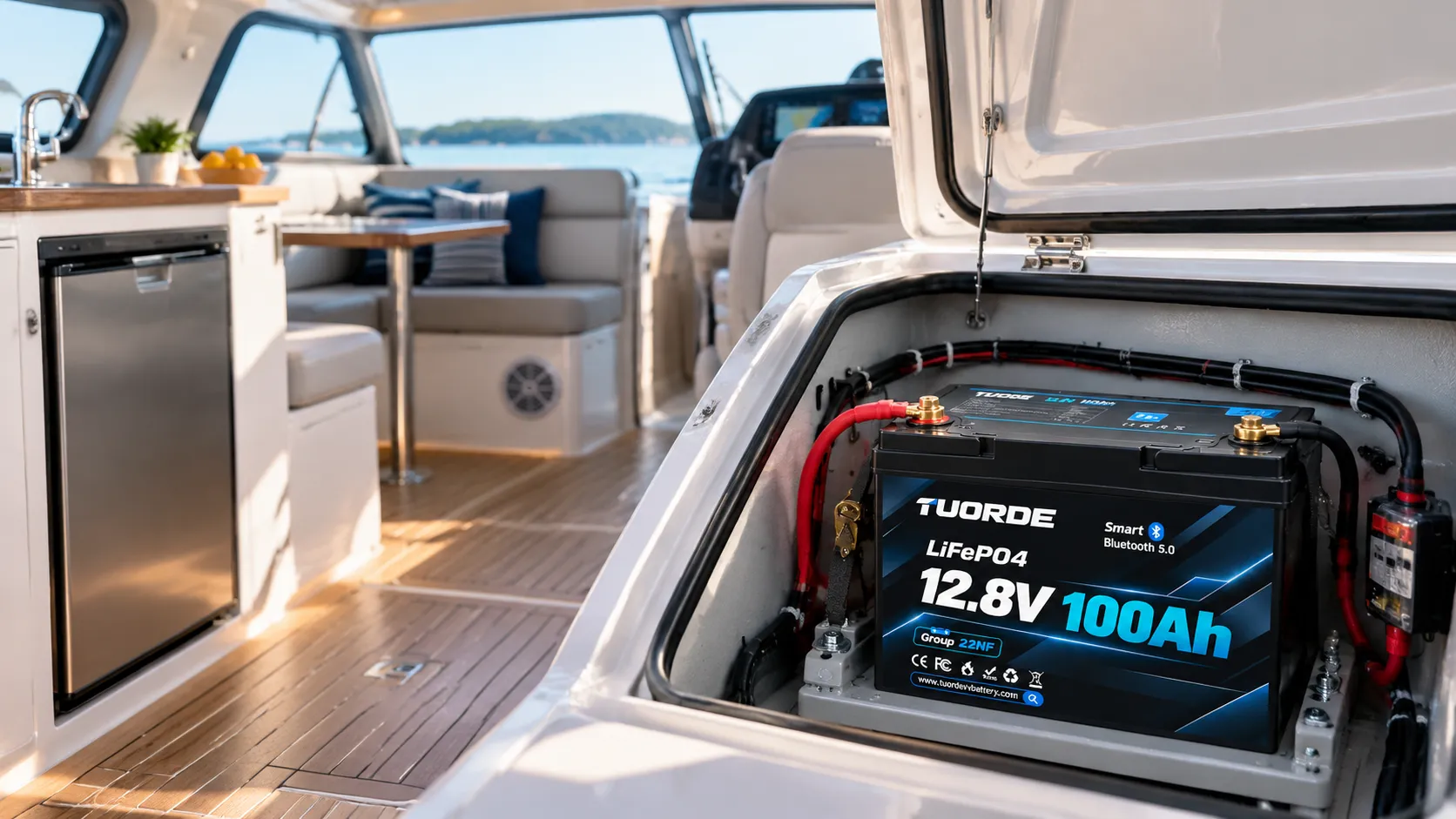
Marine house-power application illustration. Confirm the selected model, installation environment and charging architecture before integration.
This route covers house and auxiliary storage. Engine starting, electric propulsion and trolling-motor applications require separate product and system validation. An RV battery label or enclosure rating alone does not confirm marine suitability.
An off-grid upgrade needs enough stored energy for low-production periods and enough generation to replenish it. A larger battery bank cannot correct an ongoing daily energy deficit.
Design question
What to calculate or check
Information to send
How much energy is needed?
Daily AC/DC energy, continuous background demand and any loads that can be scheduled or shed.
Measured kWh/day or a complete load-and-hours list.
How long must the system run without solar?
Required autonomy in days, essential-load reserve and the approved usable battery operating window.
Desired no-sun operating period and backup policy.
Can the solar array restore the bank?
Seasonal site-specific yield, controller limits and energy available after the daily load; allow for recovery of a depleted bank.
Location, array rating/layout, solar-controller model and available production history.
Can the inverter and bank work together?
System voltage, sustained and start-up power, charging current and BMS integration.
Inverter/charger model, load surge, existing bank voltage and wiring diagram.
What happens during extended poor weather?
Generator charging capacity, recharge time, load prioritisation and any supported start/stop control.
Generator rating, charger settings and operating restrictions.
Illustrative Two-Day Storage Calculation
Assume 2kWh/day of AC loads, 2 days without charging, 90% inverter efficiency and an 80% allocation of nominal battery energy. Required nominal energy ≈ 2 × 2 ÷ (0.90 × 0.80) = 5.56kWh.
This is a planning calculation, not a TUORDE model recommendation. Add allowances for unlisted DC/standby consumption, ageing, temperature and the agreed reserve. Choose the bank voltage and approved battery configuration with the inverter requirements; do not infer series capability from the calculation.
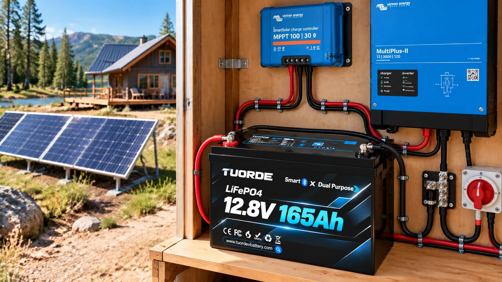
Off-grid application illustration. Equipment shown does not establish a validated wiring arrangement or inverter compatibility.
Start with the limitation in your current system. A larger battery will not correct an unsuitable charger, excessive voltage drop or a load that exceeds the battery’s current rating.
Enough usable energy for the operating period, with an agreed reserve.
Available charging does not restore the bank
Charging-source output, solar yield, charging hours, cable losses and voltage profile.
Compatible charging paths with enough energy and time to replenish the bank.
The inverter stops when an appliance starts
Start-up surge, battery/BMS limits, cable voltage drop and inverter settings.
Pack, cables and protection that support both sustained and transient demand.
Maintenance or packaging is difficult
Flooded-battery service access, tray dimensions, retention and terminal arrangement.
A maintainable installation based on the selected pack’s actual drawing and weight.
Battery condition is hard to understand
Existing monitoring, measurement points and abnormal-load history.
A defined Smart BMS/app configuration and useful operating information.
Compare the Complete Battery System
Selection factor
Existing lead-acid bank
TUORDE LiFePO4 upgrade review
Usable energy
Check actual condition and the manufacturer’s permitted discharge depth.
Use the approved operating window; compare Wh available to your loads.
Maintenance
Flooded batteries may need watering; AGM and gel differ.
No flooded-cell watering; terminals, mounting and wiring still need inspection.
Charging
Settings depend on flooded, AGM or gel design.
Confirm the selected LFP voltage profile, temperature limits and current limits.
Weight & life
Record actual bank weight and service history.
Compare approved pack weight and cycle data under stated test conditions.
System compatibility
Record existing components before removal.
Assess charging, protection, wiring and monitoring as one system.
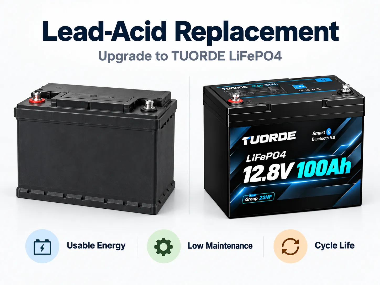
Battery comparison illustration. Usable energy, weight, life and fit must be compared using model-specific data.
Upgrade benefits depend on the selected battery and the installed system. Physical fit and matching Ah are not sufficient selection criteria.
03 / SHORTLIST THE BATTERY
Choose a Platform After the Application Review
RV Reference Platforms
Use these RV models to shortlist house-power options. Confirm configuration, fit, current limits and availability for the selected model and application.
Nominal energy is calculated from voltage × capacity; it is not measured usable energy or guaranteed runtime. These RV listings are not a declaration of marine or off-grid suitability.
Marine & Off-Grid Configuration Review
Application
Define first
Selection route
Marine house power
House-bank voltage, daily Wh, time at anchor, shore/solar/alternator architecture, environment and essential services.
Energy: enough usable Wh between charging opportunities. Power: approved continuous current and surge duration. Fit: enclosure, retention, terminals and environment. Charging: compatible equipment with enough energy and time to recharge.
Use a load list to estimate the energy needed between charging opportunities. Keep daily energy (Wh) separate from the instantaneous current needed to run appliances.
Illustrative RV Load Budget
Load
Assumed power
Daily active time
Energy at the load
DC refrigerator
45W while running
8 compressor-on hours
360Wh
DC lighting
20W combined
5h
100Wh
DC water pump
60W
0.5h
30Wh
DC ventilation
20W
6h
120Wh
AC laptop / charger
65W
4h
260Wh
These are planning assumptions, not measurements from a TUORDE installation. Measure your equipment. Refrigerator cycling and appliance usage vary; air conditioning, cooking and other loads are excluded.
1. Convert to Battery Energy
DC loads total 610Wh/day. Assuming 90% inverter efficiency, the 260Wh AC load needs about 289Wh from the battery. Total: about 899Wh/day, before unlisted standby and other losses.
2. Set an Operating Reserve
For this example only, allocating 80% of nominal energy gives 899 ÷ 0.80 ≈ 1,124Wh nominal. At 12.8V, this is about 88Ah for one day or 176Ah for two days without charging.
3. Review a Platform
A 100Ah platform enters the one-day review with limited margin. A 200Ah platform provides more nominal-energy headroom or enters the two-day review. Evaluate 280Ah for additional reserve or higher measured demand, subject to fit and current limits.
The assumed 80% allocation is not a TUORDE product rating. Final sizing must allow for temperature, ageing, standby loads, validated usable energy and your reserve policy. The linked RV platform configurations require approval.
Check Power and Recharge Time Separately
For an inverter-fed load, estimate battery current using I ≈ AC watts ÷ (battery voltage × inverter efficiency). A 1,000W load at an assumed 12.0V and 90% efficiency draws about 93A before other loads; a 2,000W load draws about 185A. Starting surge can be higher. Check the selected pack’s approved continuous and peak ratings, peak duration, cables and protection.
Restoring 100Ah with a 20A charger takes at least 5 hours in an ideal calculation. Actual time is longer when other loads draw power, the charger reduces current or losses occur. Higher capacity does not help if the available charging window cannot replenish it.
Record the make, model and settings of every charging source. Decide whether it can meet the selected battery’s approved voltage, current, temperature and control requirements.
Existing equipment
Retain or adjust when…
Replace or add equipment when…
AC converter / shore charger
Its manufacturer supports the selected LFP charging profile and its limits can be set correctly.
The charging behavior or equalization cannot be made compatible, or its output is insufficient.
Solar charge controller
The selected settings, battery voltage, array input and charging current are within the equipment and pack limits.
Its profile cannot be set appropriately, or its input/output ratings do not suit the system.
RV / marine alternator charging
Current control, regulation, isolation and charging-stop behavior have been reviewed for the chosen bank.
Direct connection imposes unsuitable current demand or control behavior; assess a compatible DC-DC charger or regulated charging arrangement.
Off-grid backup generator charging
Generator AC output and charger settings work together within the agreed load and battery-charge limits.
The generator/charger cannot support the combined loads and recharge demand; revise the operating plan or equipment.
Inverter / charger
Charging, shutdown and any supported BMS communication can be configured for the selected pack and loads.
Charge settings, sustained/surge demand or required BMS control cannot be coordinated.
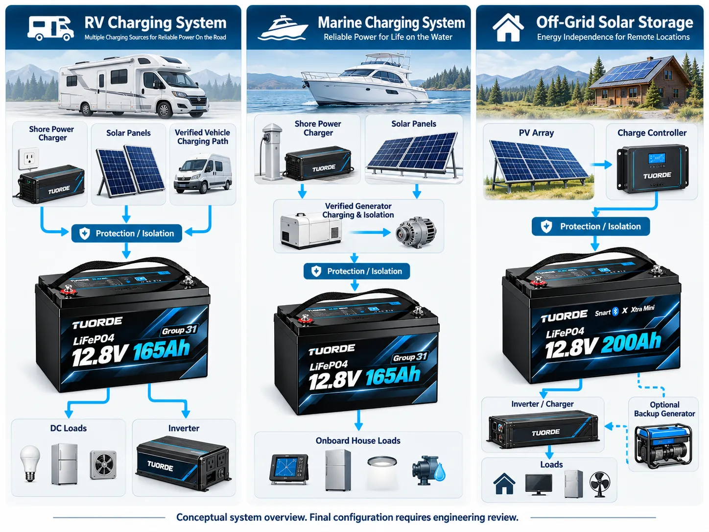
Application overview illustration only, not a validated wiring diagram. Equipment depictions, connections and charging controls require project-specific engineering review.
Submit a system diagram or clear equipment photos. Use the approved battery and equipment instructions for settings and wiring. In marine systems, explicitly review alternator behavior when charging is interrupted and the separation of starter and house functions.
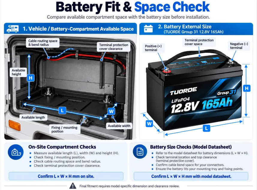
Measure usable length, width and height, including terminal covers and cable bends. Record hold-down geometry, access to disconnects, polarity and cable reach. Use the approved mechanical drawing rather than the battery-group name alone.
Check Cables & Protection
Review continuous load, surge, conductor size, cable length, voltage drop and protection coordination. The BMS does not replace correctly specified external fuses and disconnects. Do not reuse existing cables solely because they fit the terminals.
Define Climate & Bank Arrangement
Record minimum charging temperature and installation environment. Confirm low-temperature charge behavior and any heating requirement. Use only an approved series/parallel arrangement with the selected BMS and system design.
Installation fit-check illustration. Confirm actual dimensions, terminal layout and clearance using the selected model drawing.
Installation & Commissioning Review
Before installation: agree the battery configuration, wiring, charging settings, protection and mounting; follow the relevant isolation procedure.
After connection: check polarity, retention, connection torque and protective covers against the approved instructions.
During commissioning: verify each charging source, representative sustained loads and start-up behavior; record voltages, current and temperature.
At handover: retain settings, wiring revision, battery identification and any app/protocol configuration for service support.
Have the final system checked by a qualified installer. Do not directly parallel different chemistries in one battery bank. Retained starter and house batteries need an appropriately reviewed isolation and charging architecture.
Review moisture and salt exposure, vibration, retention, protected connections and the installation location with a qualified marine installer. Agree how essential services remain available when energy is low or the battery/BMS disconnects. Verify the documentation required for the vessel and market.
Off-Grid Installation & Recovery
Review temperature, enclosure access, cable/protection layout and the supported inverter/BMS configuration. Agree low-energy load priorities, backup charging and how the bank is restored after extended poor weather. Check the applicable stationary-installation requirements for the site.
07 / SPECIFY THE SMART FUNCTIONS
Make Battery Information Useful After the Upgrade
Define which operating information the user and service team need, then specify the battery’s BMS, app and communication configuration.
Function
What it helps the operator understand
What to confirm in the selected configuration
Battery status
SOC, voltage, current, temperature and operating history.
Available measurements, app access and data update behavior.
Runtime prediction
Estimated time remaining under the observed power demand.
Supported algorithm and inputs; changing loads can change the estimate.
Abnormal drain detection
Unusual consumption that deserves investigation.
Alert behavior and sufficient operating data for the application.
Health intelligence & troubleshooting
Battery condition indicators and guidance when abnormal behavior occurs.
Supported diagnostics and service workflow; diagnosis does not physically repair a fault.
CAN / RS485 integration
Battery data exchanged with compatible connected equipment.
Protocol, pinout, firmware and equipment compatibility; an interface alone does not establish integration.
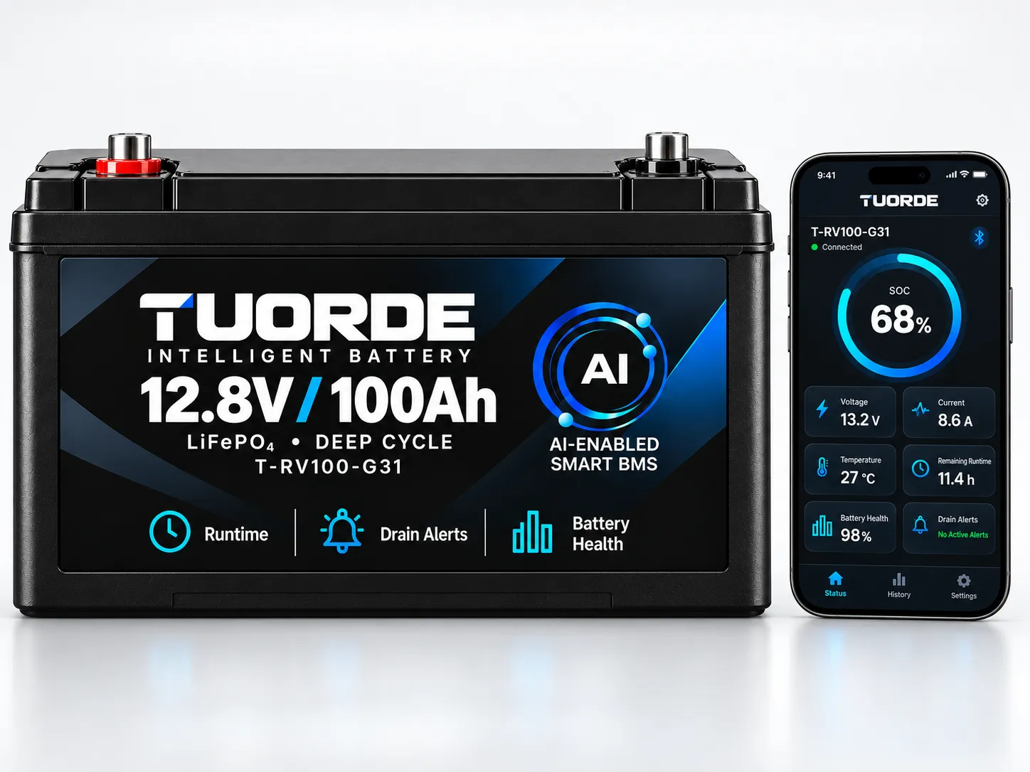
Smart BMS and app illustration; displayed values are examples. Confirm the functions supplied with the selected battery configuration.
The linked RV CORE configurations list no self-heating. Specify heating, Bluetooth and advanced functions explicitly; availability depends on the chosen hardware, firmware and software.
Request Documents for the Selected Model & Application
Match the battery configuration and report revision to the intended installation. Review application suitability separately from nominal capacity.
Specification & Fit
Request the datasheet, mechanical drawing, terminal layout, charge/discharge limits and approved bank arrangements.
Tests & Environment
Request available model-specific performance, temperature and environmental data relevant to the application. Confirm test method, conditions and scope.
Integration & Compliance
Request installation instructions, supported BMS interfaces and the applicable transport/market documentation. Distinguish component reports from finished-pack documents.
Application-Specific Evidence to Review
Application
Additional review focus
RV house power
Compartment fit, converter/solar/alternator charging and inverter load behavior.
Marine house power
Installation environment, shore/alternator charging and isolation, house-bank suitability and essential-service arrangements.
Off-grid solar storage
Inverter/BMS compatibility, usable energy under agreed conditions, installation requirements and solar/generator recovery plan.
Documents and certification scope depend on the model and market. No blanket marine approval or stationary-system compliance is claimed for the RV reference platforms.
From Existing Battery Data to an Approved Supply Configuration
For distributors, private-label brands, RV builders, marine integrators and off-grid system installers, use a documented review process so the quotation, evaluation sample and production order refer to the same configuration.
Stage
Your project information
Review output to agree
1. Application brief
Old battery label and bank arrangement; duty, load list, required runtime, charging sources and climate.
Application requirements and an initial platform shortlist.
2. Engineering review
Compartment drawing/photos, terminals, cables/protection and required interfaces.
Configuration proposal, integration changes and unresolved validation items.
Quotation, MOQ, sample scope, documentation requirements and lead time for confirmation.
4. Sample evaluation
Agreed test conditions and acceptance criteria for the actual application.
Recorded fit, energy/load, charging, thermal and communication results; application-specific environmental and system-behavior checks.
5. Production approval
Accepted sample results, final drawing/BOM configuration, artwork and packaging.
Approved specification and revisions, quality criteria and production/delivery plan.
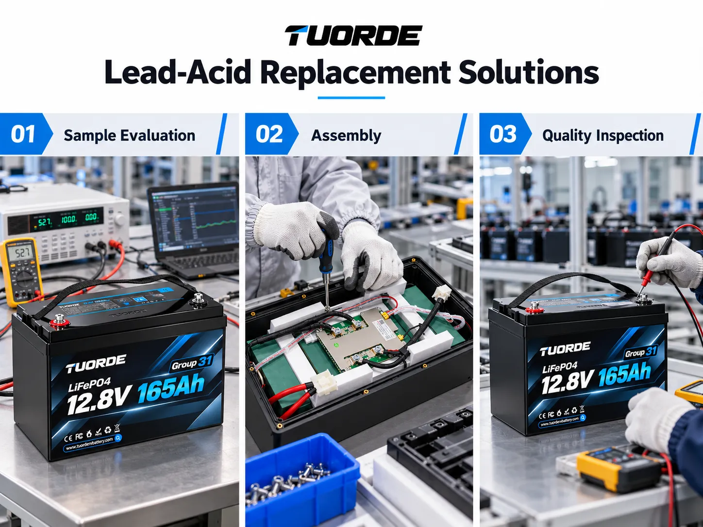
OEM workflow illustration. Instrument readings shown are not submitted model-specific test evidence; request actual validation records for the selected pack.
These stages describe the proposed cooperation workflow. Sample availability, validation scope, tooling, price and delivery timing are confirmed for the project.
Review its make, model, settings and behavior against the selected battery. It may be retained or adjusted if the manufacturer supports suitable LFP settings and limits. Review solar, alternator and generator charging separately.
Should I match the old bank’s Ah rating?
Start with usable energy, daily load and time between charging opportunities. Ah comparisons require the same nominal voltage. Also review current limits, charging, environment and physical fit.
Can the listed RV batteries be used in a boat?
The RV listings are reference platforms for RV duty. Marine house-bank use requires a separate review of the exact configuration, installation environment, charging/isolating equipment and vessel requirements. An RV listing is not a marine approval.
Does marine house power include engine starting or propulsion?
This page covers house and auxiliary energy storage. Engine starting, electric propulsion and trolling-motor use require separate product and system validation; no suitability is assumed.
How do I size an off-grid battery bank?
Estimate daily AC/DC energy and the required days without charging, then allow for conversion losses, the approved usable operating window, reserve, temperature and ageing. Review bank voltage and inverter/BMS requirements together.
Will a larger battery solve low solar production?
A larger bank stores more energy but does not generate it. Compare seasonal solar yield with daily consumption and the energy needed to recover after poor weather. Review backup-generator charging and load priorities where required.
Does a 200Ah battery support a 2,000W inverter?
Capacity alone does not establish power capability. At an illustrative 12.0V and 90% inverter efficiency, a 2,000W load requires about 185A before other loads and surge. Use validated pack limits, peak duration and the approved cabling/protection design.
Can lithium and lead-acid batteries share one bank?
Do not directly parallel different battery chemistries in one bank. If a separate starter or other bank is retained, have the isolation and regulated charging arrangement reviewed for the application.
Do RV and marine systems always need a DC-DC charger?
The equipment depends on the alternator/regulator, current limits, isolation and selected battery. Assess current control and behavior when charging stops. A compatible DC-DC charger may form part of the reviewed architecture.
Can the battery charge below freezing?
Follow the exact battery’s approved charge-temperature limits. Heating must be specified and its operation confirmed. The linked RV CORE configurations list no self-heating.
Will CAN or RS485 work with my inverter automatically?
No. Confirm the protocol, pinout, hardware, firmware and supported equipment for the selected battery configuration. An interface name or connector alone does not establish compatibility.
What should I send for an OEM quotation and sample?
Send the application, old bank specification and wiring, daily energy/load profile, charging equipment, installation details, target market and quantities. For marine add vessel/environment and essential services; for off-grid add location, autonomy target, solar and generator details. Agree sample tests and documentation before production approval.
11 / START YOUR REPLACEMENT PROJECT
Send Your Battery, Charging & Application Details
Share your application, old battery bank voltage/capacity, load list, charging equipment, installation space, target market and expected quantity. Add a selected model where known; marine and off-grid projects can start with a configuration review.
Inquiry links include the application for your review before sending. Model-specific links also include the selected model. Sample scope, MOQ, price and lead time are agreed after configuration review.