

01
Starting Energy Reserve
Selected configurations limit parking-load discharge at a configured SOC threshold to help retain starting energy. Reserve settings require application review and do not guarantee a start in every condition.
TRUCK STARTING & PARKING BATTERIES
Starting demand. Parked loads. One coordinated battery solution.
TUORDE ST230, ST150 and ST125 are commercially available 24V LiFePO4 truck batteries combining engine starting and deep-cycle parking power, with model-specific Smart BMS protection, monitoring options and OEM customization.
For commercial vehicle manufacturers, fleet partners, battery distributors and private-label brands.
01 / DEFINE THE DUTY
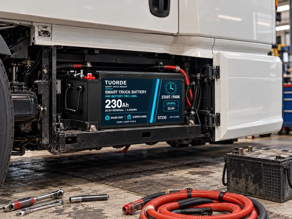
A starting and parking battery must address a short engine-starting event and sustained auxiliary energy use. Evaluate both duties together with the vehicle charging system.
Review the vehicle starting demand, required current duration, operating temperature and permitted voltage behavior. Capacity alone does not establish starting capability.
Define the sleeper-cabin and auxiliary loads, their average consumption and the required parked operating time. Include conversion losses and the configured energy reserve.
Check alternator and charger compatibility, charging voltage, current limits and the time available to replenish the battery before the next duty cycle.
02 / COMPARE THE PLATFORMS
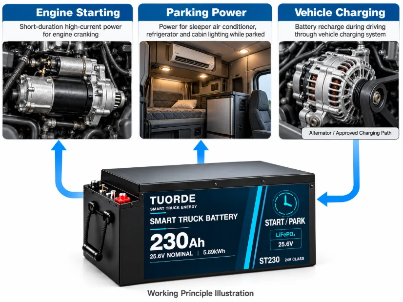
These commercially available truck battery platforms combine starting and parking duties. Compare rated energy first, then confirm starting performance, current limits and mechanical fit for the exact model.
| Model | Nominal voltage | Rated capacity | Nominal energy | Project inquiry |
|---|---|---|---|---|
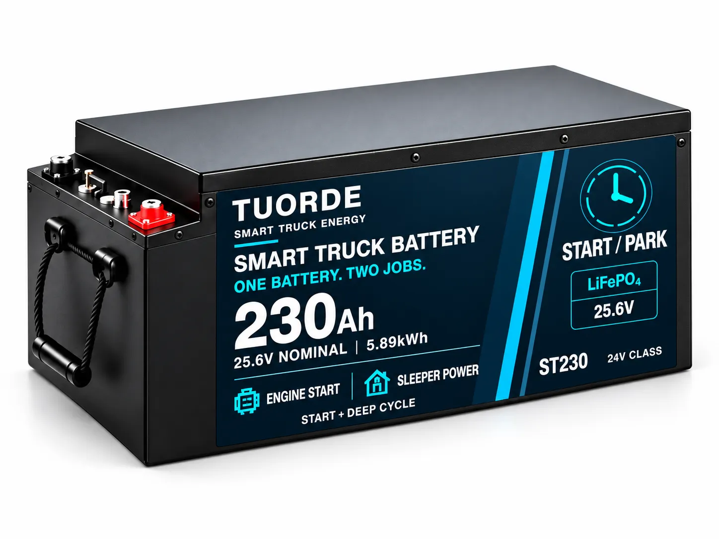 ST230 specifications → | 25.6V | 230Ah | 5.89kWh | Discuss ST230 → Highest nominal energy of these three models for greater parked-load demand. |
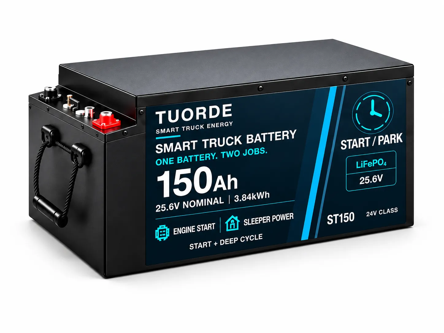 ST150 specifications → | 25.6V | 150Ah | 3.84kWh | Discuss ST150 → Mid-range nominal energy in this comparison; match parked loads to the available recharge window. |
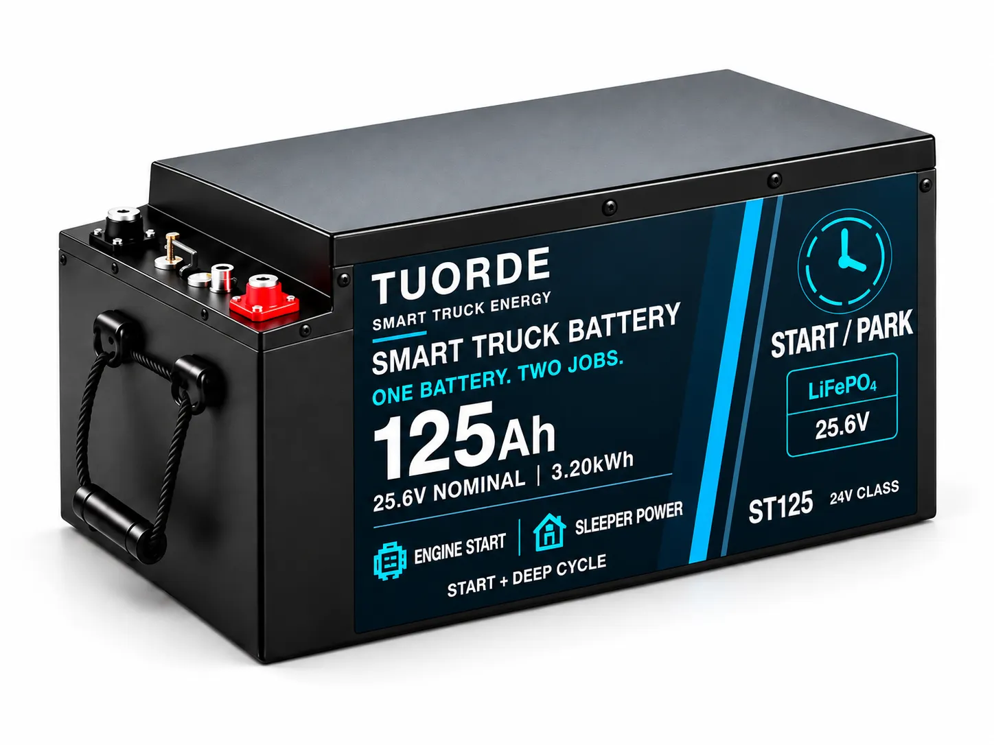 ST125 specifications → | 25.6V | 125Ah | 3.20kWh | Discuss ST125 → Lower nominal energy in this comparison for defined auxiliary loads; confirm starting requirements separately. |
Nominal energy = nominal voltage × rated capacity; values shown are rounded. Usable energy and runtime depend on load, temperature, conversion losses and protection or reserve settings. Request the model datasheet for dimensions, weight, starting ratings and charge/discharge limits. Browse AI Smart Truck Batteries for the current product range.
Use measured average loads and duty cycles where possible. The following figures are illustrative planning assumptions, not TUORDE runtime test results.
| Illustrative load | Assumed average power | Operating time | Battery-side energy |
|---|---|---|---|
| DC parking cooler | 350 W | 8 h | 2,800 Wh |
| DC refrigerator | 45 W | 8 h | 360 Wh |
| DC electronics | 30 W | 4 h | 120 Wh |
| DC lighting | 10 W | 4 h | 40 Wh |
| Small AC load through inverter | 100 W AC; assumed 90% efficiency | 1 h | 111 Wh |
Estimated parking demand: 3,431 Wh, or about 3.43 kWh. This excludes the separately determined starting reserve, other conversion losses, inverter standby consumption and any additional design allowance.
ST125 stores 3.20 kWh nominally, so it cannot meet this example on nominal energy alone. ST150 provides only about 0.41 kWh of nominal headroom before the permitted usable window and starting reserve are considered. ST230 is the higher-energy candidate to assess, subject to starting capability, current limits, temperature and fit.
Parking runtime ≈ energy available for parking ÷ average battery-side load. Energy available for parking must account for the agreed operating limits and starting reserve. Do not use the nominal kWh figure as guaranteed usable energy.
For an illustrative 3.43 kWh replenishment requirement, a hypothetical 1.0 kW battery-side charging input would require at least 3.43 hours before tapering or interruptions. If 0.25 kW of loads remain active, net replenishment is only 0.75 kW and the theoretical time becomes about 4.57 hours.
Use the vehicle’s measured charging behavior and approved limits for the real calculation. If daily replenishment is below daily consumption, review charging capacity, driving time or loads before increasing battery capacity.
03 / SELECT THE INTELLIGENCE
Specify the functions your application needs during configuration. Communication hardware, heating and diagnostic functions must be confirmed for the selected battery and vehicle system.
01
Selected configurations limit parking-load discharge at a configured SOC threshold to help retain starting energy. Reserve settings require application review and do not guarantee a start in every condition.
02
Supply compatible sleeper-cabin and parked-vehicle loads. Match sustained demand, inverter requirements and protection settings to the selected model.
03
Include any remote monitoring or preheating requirement in the engineering brief. Confirm available hardware, firmware, connectivity, supported conditions and vehicle integration before including these functions in the order.
04
Monitor battery voltage, current and temperature conditions. Use the selected model’s documented protection limits and operating instructions.
05
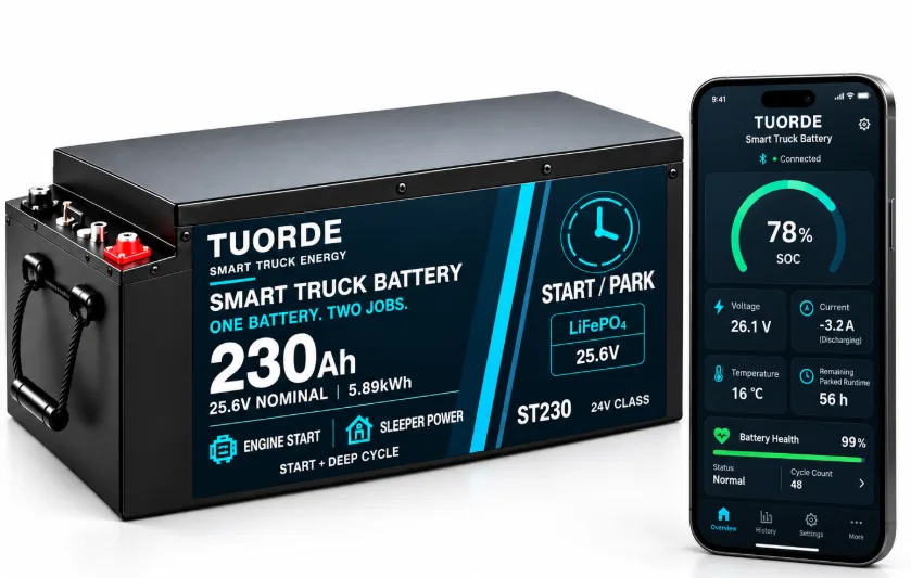
Selected configurations provide runtime estimates, abnormal drain alerts, battery health insights and One-Tap Smart Troubleshooting for diagnostics and guided solutions. Specify Bluetooth, CAN or RS485 interfaces where supported.
Feature availability depends on the battery model, BMS hardware, firmware, software and integration. Guided diagnostics do not perform automatic battery repair. For the truck battery control and monitoring architecture, explore Smart BMS & AI Truck Battery Technology →.
04 / CONFIRM VEHICLE INTEGRATION
Before replacing a lead-acid starting battery arrangement, review the complete vehicle electrical system with a qualified installer and the relevant equipment documentation.
Vehicle system voltage, starting demand and duration, low-temperature requirements and acceptable voltage behavior.
Load list, operating hours, inverter demand, load isolation and the SOC reserve strategy.
Charging voltage and current, alternator control, battery isolation and any required charging interface.
Battery tray dimensions, terminal position, cable reach, securing hardware and service clearance.
Cable sizing, fusing, connections and protection coordination for both starting and auxiliary circuits.
Supported charge/discharge temperatures, heating configuration, communication protocol and connected equipment.
Do not assume drop-in compatibility, series/parallel capability or charger compatibility without model-specific confirmation. Starting-current and vehicle-compatibility claims require the relevant technical documentation.
| Equipment / interface | May remain when… | Review settings, replacement or additions when… |
|---|---|---|
| Alternator & vehicle charge control | Voltage behavior, current capability, control strategy and protection are compatible with the selected battery and vehicle duty. | The battery requires current limiting, voltage conversion, isolation or revised control. Assess the correct charging interface for the vehicle rather than inserting a generic charger into the engine-starting path. |
| External charger / auxiliary charging | Its documented profile and current settings meet the approved battery requirements. | An incompatible fixed profile or equalization / desulfation mode cannot be disabled, or permitted voltage and current limits cannot be met. |
| Starter circuit & battery monitoring | The approved design preserves required cranking performance, voltage behavior and vehicle monitoring functions. | Protection, switching or monitoring may interrupt starting or conflict with the vehicle control system. Review the vehicle architecture and exact battery protection / recovery behavior. |
| Parking loads & inverter | Continuous and startup demands fit the battery, BMS, wiring and agreed energy reserve. | Peaks cause trips, low-voltage settings conflict with the battery, or parking loads need a separate control / isolation strategy to preserve starting energy. |
| Tray, terminals, cables & protection | Mounting, terminal access, cable reach and the electrical ratings match the revised installation. | Dimensions, current paths or protection coordination change. Agree cable, fuse and switching arrangements for starting and auxiliary circuits separately. |
| Communication & diagnostics | Connector, electrical interface, message mapping and firmware match the agreed host equipment. | A Bluetooth, CAN, RS485 or remote-connectivity requirement has not been verified for the exact combination. |
Vehicle integration should produce an approved drawing, equipment / settings list and protection strategy. Use the battery and vehicle documentation for the actual installation; this comparison is not a wiring instruction.
05 / CONFIGURE, VALIDATE & RELEASE
Start with the commercially available ST125, ST150 or ST230 range, then define any integration or private label changes. Each stage should close a decision before the project advances.
| Stage | Customer input | Output to agree |
|---|---|---|
| 1. Submit the duty profile | Vehicle / engine details; existing battery arrangement; starting demand; parking loads; temperatures; charging equipment; drawings; quantities and market. | Project brief, missing-data list and an initial platform shortlist. |
| 2. Review the configuration | Vehicle documents, measured loads / charging behavior and required monitoring / communication functions. | Proposed model and revision, operating limits, dimensional / terminal drawing, integration changes and quotation assumptions. |
| 3. Validate the sample | Representative vehicle or test setup and agreed starting / parking duty cycles. | Evaluation plan and records covering starting voltage behavior, current versus time, parking energy, reserve / recovery, charging, temperatures and relevant communication. |
| 4. Approve the configuration | Sample findings, agreed corrections, label / packaging artwork and document requirements. | Approved configuration and revision, acceptance criteria, artwork and installation / charging guidance. Review material changes for revalidation. |
| 5. Release production & delivery | Confirmed order scope, market / transport documentation and delivery requirements. | Agreed inspection / release records, model identification / traceability, packing documentation and support route. |
Sample cost, MOQ, lead time, warranty and delivery terms depend on the selected configuration and project scope. Confirm them in the quotation and order documents.
06 / REVIEW MODEL-SPECIFIC EVIDENCE
TUORDE’s ST125, ST150 and ST230 range is commercially available following starting and parking testing. Match the supporting record to the exact model, configuration and conditions required by your project.
| Evidence to request | What the record should identify | What it helps confirm |
|---|---|---|
| Engine-starting evaluation | Battery model / revision, test temperature and initial state, engine or load setup, current versus time, minimum voltage and repeat-start conditions. | Whether the tested starting duty is relevant to the intended vehicle. An isolated peak-current number is insufficient. |
| Parking-load & reserve evaluation | Average / peak loads, duration, energy delivered, temperature, configured reserve and load-control / recovery behavior. | How much parking duty was demonstrated and what conditions remain available for the next start. |
| Vehicle charging & recovery | Vehicle / charger model, settings, charge current and voltage over time, active loads and battery protection / reconnection behavior. | Compatibility with the charging window and the agreed response to protection or interrupted charging. |
| Monitoring & communication | Battery / BMS / firmware revision, supported functions, host equipment and protocol or App recording. | Which features work on the quoted configuration and what requires integration work. |
| Installation & market documents | Current datasheet, dimensional drawing, installation / charging instructions and applicable transport / compliance document scope. | Fit, operation and documentation requirements for the exact model and destination. |
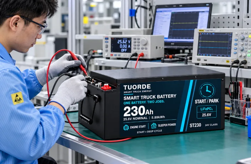
Request available original records or agree additional sample validation where the project conditions differ. Add public test images, videos and customer cases only when approved material is available.
07 / ENGINEERING QUESTIONS
It is a battery platform intended to support both engine starting and repeated auxiliary-load use while the vehicle is parked. The selected battery must be validated for the starting system, parked loads and charging equipment of the specific vehicle.
A dual-purpose configuration may support both duties in a compatible vehicle system. It is not an automatic replacement for every battery arrangement. Review wiring, charging control, load isolation, protection settings and vehicle requirements before installation.
The truck platforms shown here are ST230, ST150 and ST125, with rated capacities of 230Ah, 150Ah and 125Ah respectively at 25.6V nominal voltage. Confirm the final model datasheet, current ratings and installation drawing before selection.
No. Amp-hour capacity and nominal energy describe energy storage. Starting capability must be assessed using the relevant current-versus-time ratings, temperature conditions, vehicle demand and model-specific validation information.
Selected truck configurations limit parking-load discharge at a configured SOC threshold to help retain energy for the next engine start. Reserve settings require vehicle-specific review and do not guarantee a successful start under all conditions.
It should not be assumed as standard. Include remote preheating in your requested scope and obtain confirmation of availability, heating hardware, BMS firmware, connectivity and vehicle integration for the quoted configuration.
No. Monitoring, communication and diagnostic features depend on the selected battery model, BMS hardware, firmware and software. Confirm the required interfaces and functions during quotation. Guided diagnostics do not perform automatic battery repair.
Share the vehicle and electrical system, starting requirements, parked loads, desired runtime, charging equipment, installation dimensions, operating temperatures, expected quantity and branding or communication requirements. Our team can then review the appropriate battery configuration.
Runtime requires the actual battery-side load profile, permitted usable energy, temperature, inverter losses and configured starting reserve. Use the worked example to prepare a load budget, then request the model-specific evaluation. Nominal energy alone is not a runtime guarantee.
That depends on the vehicle charging architecture and the approved battery limits. Provide the alternator / charger details, voltage behavior, current profile and control information. Engineering review should identify what can remain, what settings must change and whether a charging interface is required.
Treat local Bluetooth monitoring and remote connectivity as separate requirements. Confirm the communication hardware, software, network arrangements and supported functions for the quoted configuration; a Bluetooth interface does not establish remote monitoring or heating capability.
Approve the exact model and revision, vehicle integration drawing, operating limits, sample validation results and acceptance criteria, communication / monitoring scope, artwork and required documents. Confirm commercial terms and identify changes that require further validation.
START WITH YOUR APPLICATION
Send your vehicle requirements, starting demand, parked loads, installation dimensions and expected quantity. TUORDE engineers can help review the appropriate battery platform and configuration.
Request a Truck Battery QuoteFor RV and camper house power, explore RV Lithium Battery Solutions →