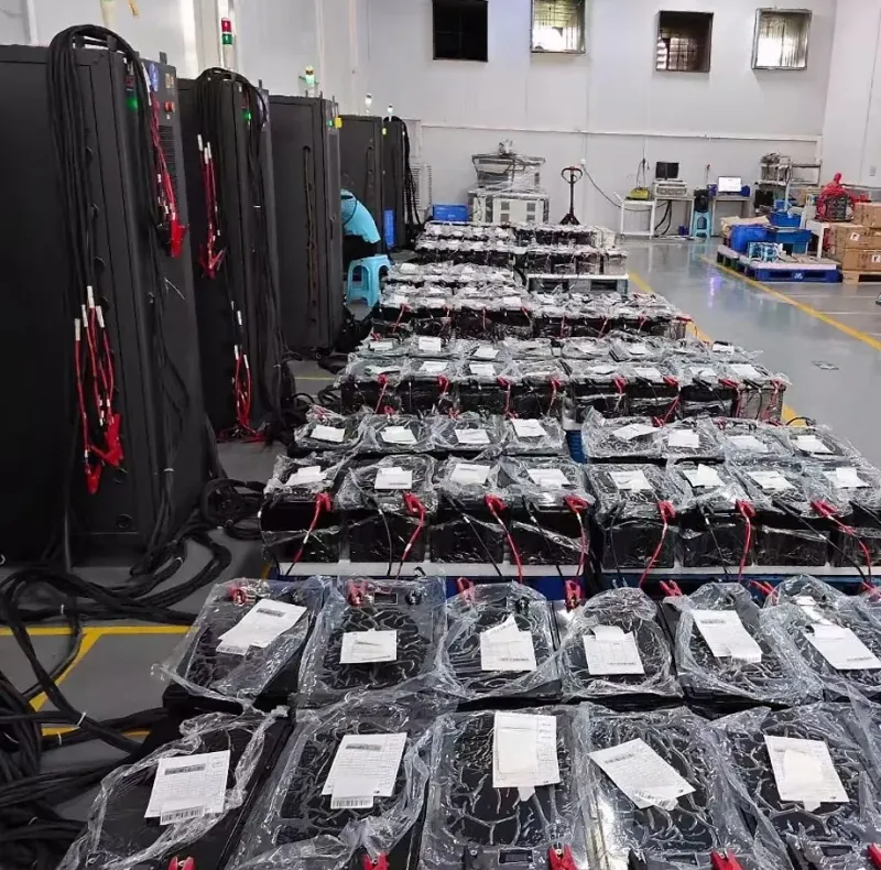

Cover image: application illustration; not model-specific installation or test evidence.
SMART BMS & INTEGRATION
A continuous current rating describes sustained operation under specified conditions. A peak rating describes a limited event, and it is incomplete without its duration and test conditions. A BMS trip threshold is a protection setting, not a current level that the finished battery is automatically rated to supply.
These distinctions matter when distributors, inverter integrators and vehicle manufacturers compare battery proposals. Start with the load’s current/time requirement and the complete pack rating. Do not select a battery from a BMS marketing label alone.
1. Separate four different specifications
| Term | What it describes | What to request |
|---|---|---|
| Continuous current | Sustained charge or discharge capability under defined conditions | Direction, ambient/cell temperature, cooling, voltage/SOC range and any derating. |
| Peak current | A permitted short-duration operating event | Amplitude, duration, repetition interval, initial conditions and minimum voltage. |
| Protection threshold and delay | Conditions that cause an alert or disconnect | Threshold tolerance, timing, temperature dependencies and short-circuit behavior. |
| Recovery behavior | How operation resumes after a protection event | Automatic or controlled recovery, reset conditions and host-equipment response. |
Texas Instruments’ BQ76952 reference manual, for example, describes separate overcurrent and short-circuit protection thresholds, delays and recovery controls. It illustrates the distinction between protection logic and operating ratings. It does not identify the electronics fitted to any TUORDE model or establish that model’s output capability.
2. Check the whole current path
Cells, interconnections, the BMS switching stage, terminals, cables and protection devices all participate in the same load path. The usable system rating must respect each component’s validated operating conditions. A fuse’s nominal current is not a substitute for its time/current behavior, and a BMS must not be assumed to replace all required external protection.
- Ask whether a published rating belongs to a cell, a standalone BMS board or the assembled battery.
- Check charge and discharge separately; their permitted currents may differ.
- Review terminal and conductor limits, installation temperature and cooling assumptions.
- Request permitted parallel arrangements, current-sharing requirements and the response if one battery disconnects.
Counting MOSFETs or reading cell Ah capacity cannot establish a finished-pack current rating. In parallel systems, current sharing depends on the actual electrical paths and operating state. Victron’s battery-bank wiring guidance demonstrates why connection resistance matters; it does not validate a particular TUORDE parallel arrangement. Multiplying one pack’s rating by the pack count is insufficient without an approved system design.
3. Work from AC load to battery-side current
| Assumed operating point | Calculation | Approximate battery current |
|---|---|---|
| 1,000W AC at 12.0V DC | 1,000 ÷ (12.0 × 0.90) | 92.6A |
| 1,000W AC at 10.5V DC | 1,000 ÷ (10.5 × 0.90) | 105.8A |
| Hypothetical 2,000W surge at 10.5V | 2,000 ÷ (10.5 × 0.90) | 211.6A during that event |
For this simplified constant-power example, current rises as battery voltage falls. Actual efficiency varies with load and voltage; voltage drop, standby demand and other DC loads change the result. If the hypothetical surge lasts one second, its battery-current requirement must be assessed for that duration and repetition rate. A ten-millisecond peak rating would not answer that question.
Do not treat these values as a final BMS size. Determine the real minimum permitted voltage at the inverter, obtain its continuous and surge characteristics, add simultaneous loads and apply the battery’s documented temperature and installation limits. Agree the complete operating envelope with the supplier.
4. Distinguish inverter surge from engine starting
An inverter starting a motor or energizing input capacitors presents its own waveform and control behavior. An engine starter presents a different mechanical and electrical duty, often with different voltage and temperature requirements. A battery qualified for an inverter event is not automatically qualified to crank an engine. A one-second peak figure is not a CCA rating.
For starting applications, ask for the relevant current-versus-time and voltage evidence under stated conditions. For inverter applications, match the inverter demand to the battery, wiring and protection response. Avoid repeated protection trips as a normal operating strategy; resolve the mismatch instead.
5. Ask for a useful current-rating package
- Finished-battery continuous charge and discharge ratings, model and document revision.
- Peak current with time limit, repetition/cool-down conditions, starting SOC, temperature and minimum voltage.
- Relevant overload/short-circuit thresholds, delay ranges and recovery procedure.
- Derating conditions and terminal, cable, fuse and mounting requirements.
- Evidence for the intended inverter or starting duty, and any approved multi-battery configuration.
Use Technical Datasheets & Downloads to identify the selected-model document, then discuss the host equipment through Smart BMS & AI Battery Technology. Communication features and protection behavior must be confirmed for the exact configuration.
Sources and application limits
The official documents below support the technical distinctions discussed here. Their product-specific limits and settings belong to those manufacturers; they are not TUORDE specifications. Use the current manual, approved battery datasheet and project drawing for the actual equipment combination.
- Texas Instruments — BQ76952 Technical Reference Manual, Rev. B
- Victron Energy — Wiring Unlimited: battery bank wiring
- ODYSSEY Battery — Frequently Asked Questions: cranking rating definitions
Talk to Battery Engineers
Send the load or inverter model, continuous power, surge magnitude and duration, permitted DC voltage range, simultaneous loads, operating temperature and proposed battery arrangement. Include the current-rating document you want us to review.
Talk to Battery Engineers